In modern industrial production, metal forming technology plays a vital role, which involves sheet metal working, metal processing and many other aspects. Especially metal stamping process, its high efficiency and accuracy is highly respected in the manufacturing industry. All of this is inseparable from the careful design and manufacture of stamping dies, especially the application of progressive stamping die, which makes the continuity and automation level of metal molding increased dramatically. In such a technology-intensive field, the importance of mechanical design is self-evident. It is not only related to the precision and durability of the stamping die, but also directly affects the quality and productivity of the final product. Therefore, the innovation and optimization of mechanical design plays a decisive role in improving the overall level of metal forming, sheet metal fabrication and metal stamping.
A mechanism is said to be planar if all the members composing it move in the same plane or in planes parallel to each other. A mechanism is a system of members with definite motions, whose constituent elements are the members and the moving parts. All members of the plane of motion are parallel to each other, the mechanism is also known as the plane mechanism, otherwise known as the space mechanism.
1, member
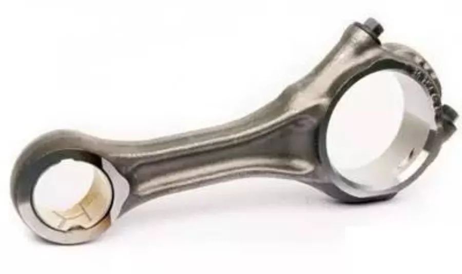
Member is a mechanism relative to each other's motion unit body. A component can be a separately manufactured parts, such as connecting rods; can also be composed of a number of parts connected to the composition of the combination.
2, motion vice
Institutions must be determined between the relative motion of the components, therefore, the connection of the components should be both direct contact between the two components, but also to produce a certain relative motion, this direct contact with the activities of the connection is known as the movement of the vice. Bearing rolling body and inner and outer ring raceway, meshing in a pair of tooth profile, slider and guide), are maintained in direct contact, and can produce a certain relative motion, thus constitute a motion vice.
3, plane mechanism movement sketch
Engineering usually does not take into account the shape of the components, cross-section size and the actual structure of the movement of the vice, only with the provisions of the simple lines and symbols of the components of the agency and the movement of the vice, and according to a certain proportion of the relative position of the movement of the vice and the relative position of their relative movement of the graphic relationship, which indicates the relative movement of the agency between the components of the relative movement of the relationship between the simple graphic, known as the agency's movement diagram. Mechanism motion sketch to maintain the movement characteristics of the actual mechanism, it concisely expresses the movement of the actual mechanism.
Steps for drawing the kinematic sketch of a plane mechanism:
Analyze the structure and movement of the mechanism, to find the active parts, follower parts and frame, to determine the relationship between the movement; to determine the number of components in the mechanism and the type and number of movement vice; select the view plane; select the appropriate scale, draw the mechanism movement sketch;
4、Hinged four-bar mechanism
The four-bar mechanism in which all four members are linked together by rotating vice is called hinged four-bar mechanism. It is the most basic form of four-bar mechanism, other forms of four-bar mechanism can be regarded as the evolution of its basis.
Hinged four-bar mechanism, according to the different forms of linkage rod movement, can be divided into crank-rocker mechanism, double-crank mechanism and double-rocker mechanism three basic forms.
5, the evolution of the hinge four-bar mechanism
Through the inversion of the connecting rod mechanism, change the relative length of the rod or change the form of the motion sub-methods, evolved from the hinged four-bar mechanism, a typical example is the crank-rocker mechanism evolved into a crank-slider mechanism.
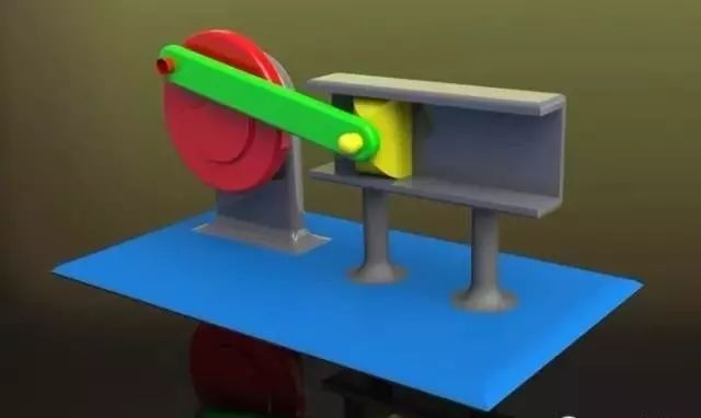
Crank slider mechanism is a crank and slider to realize the rotation and movement of mutual conversion of the plane linkage mechanism, also known as crank linkage mechanism.
Crank-slider mechanism with the frame constitutes a mobile vice member for the slider, through the rotation vice A, B link crank and slider member for the connecting rod.
Application and function: the crankshaft in the internal combustion engine is the crank, the connecting rod is the connecting rod, and the piston is the slider. The role of the pressure generated by the combustion of air driven piston linear motion is converted to rotary motion, the engine is turned.
Air compressor: crankshaft for the crank, connecting rod for the connecting rod, piston for the slider, the role of which is to convert rotary motion into linear motion, compressed air.