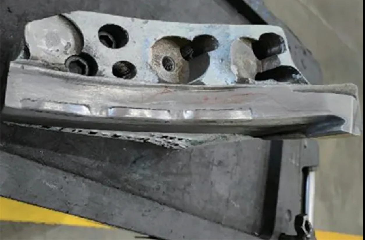
With the rapid development of the domestic automobile industry in the past decade, its appearance styling has also received more and more attention from the general public and is one of the most important factors influencing consumers' purchasing decisions. As consumers pay more attention to the appearance, defects in the appearance of parts are also highly valued by all automobile companies, and the evaluation standard of consumers' perception is constantly improved. This makes the stamping process and mold structure, which have a direct impact on the appearance of the part, put forward higher demands, requiring no appearance defects in the stamped part, the UQA evaluation score must be low.
Changes in the mold structure have different effects on the flow of sheet material during the forming process. Engineers control the sequence of material flow through changes in the mold structure and mold profile during the design and commissioning process to meet the final requirements.
Principle of flanging mold structure
This paper introduces a new flanging structure, through a reasonable arrangement of time-sequential flanging, effectively solves the side panel taillight R corner surface generated by the depression or wrinkles, in order to improve the smoothness of the R corner of the region.
Vehicle exterior shape is usually curved, small R corner highlights the sharpness of the prongs, for assembly, welding and other matching needs to be some lap edge to achieve the demand. Vehicle side panel taillight area for flanging, to be flanging area including short side region and long side region, the end of the long side region away from the flanging line, i.e., the long side of the region protrudes from the flanging line for a longer distance, which can be used as a welding surface for flanging and taillight fixing plate for welding; short side of the region close to the end of the flanging line, when flanging the long side of the region to provide support, and flanging to keep the R corner area after the flanging. The end of the short side area is close to the flanging line, which is used to provide support for the long side area when flanging and keep the R corner area intact after flanging.
Application of flanging mold structure technology
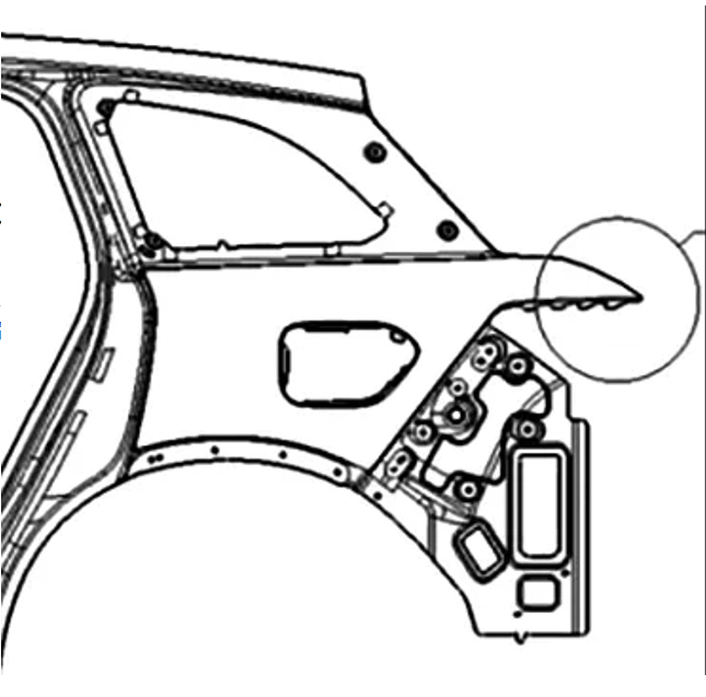
Vehicle side panel (Figure 1) tail light area of the flanging process, through the flanging die on the long side of the region and the short side of the region for simultaneous stamping flanging, but the material in the forming process of the long side of the region and the short side of the region of the material away from the material speed is not the same as the long side of the region of the elastic deformation of the region of the long side of the larger material to the short side of the region of the extrusion of the accumulation of materials, so that the flanging of forming the surface of the vehicle side of the outer panel of the taillight corner region is easy to produce concave or wrinkled, see Figure 2. Therefore, how to avoid the surface of the R corner area of the tail lamp of the vehicle side panel after flanging molding to produce depression or wrinkles, so as to improve the smoothness of the R corner of the tail lamp area of the vehicle side panel, is a problem that needs to be solved.
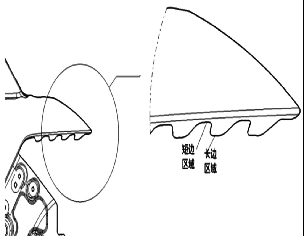
The area to be flipped includes a short side area and a long side area, and the end of the long side area is far away from the flipping line, i.e., the long side area protrudes from the flipping line for a longer distance, which can be used as a welding surface for welding with the taillight fixing plate after flipping; and the end of the short side area is close to the flipping line, which is used to provide support for the long side area during flipping and to maintain the appearance of the R-corner area intact after flipping.
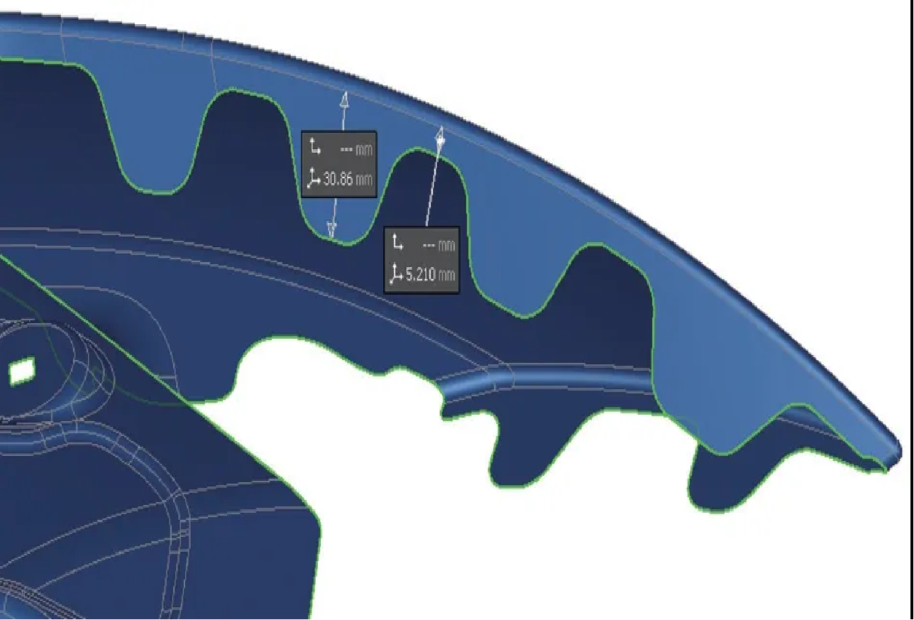
This product taillight area profile with a large arch, at the same time, due to the torch accessibility requirements, taillight flange length of 30mm, for all recent side parts in the deepest, need to increase the gap in the middle of the weld joints in order to solve the press flanging process of the curved surface of the aggregated material caused by wrinkles, the gap drop of 25mm, as shown in Figure 3.
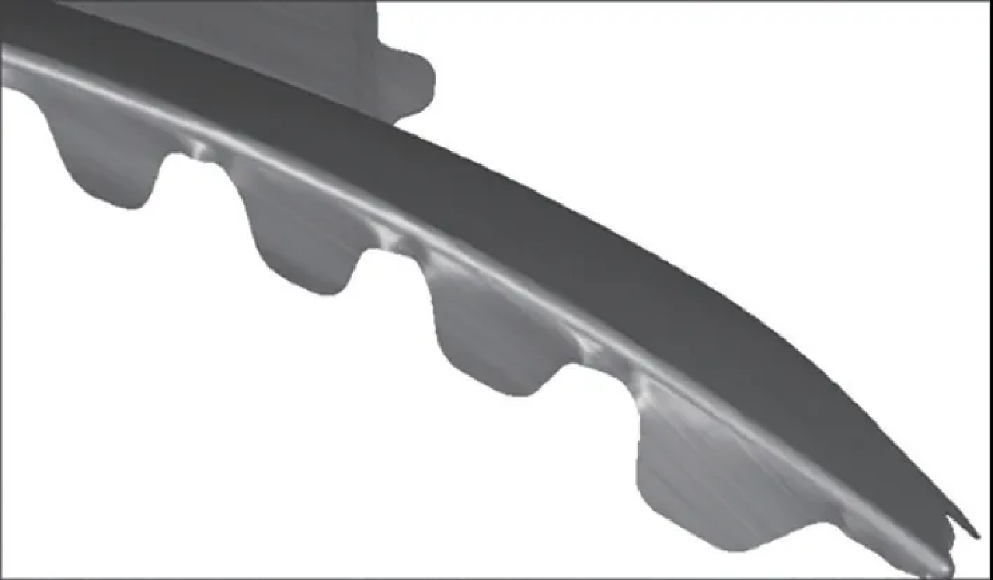
The general process route is direct flanging, one-time molding completion, but in the flanging process of the short side position will appear serious wrinkle problem, as shown in Figure 4.
The solution adopted in this case is a time-sequential flanging, where the first time the fillet is flipped out and the second time the flange face is flipped into place, as shown in Fig. 5.
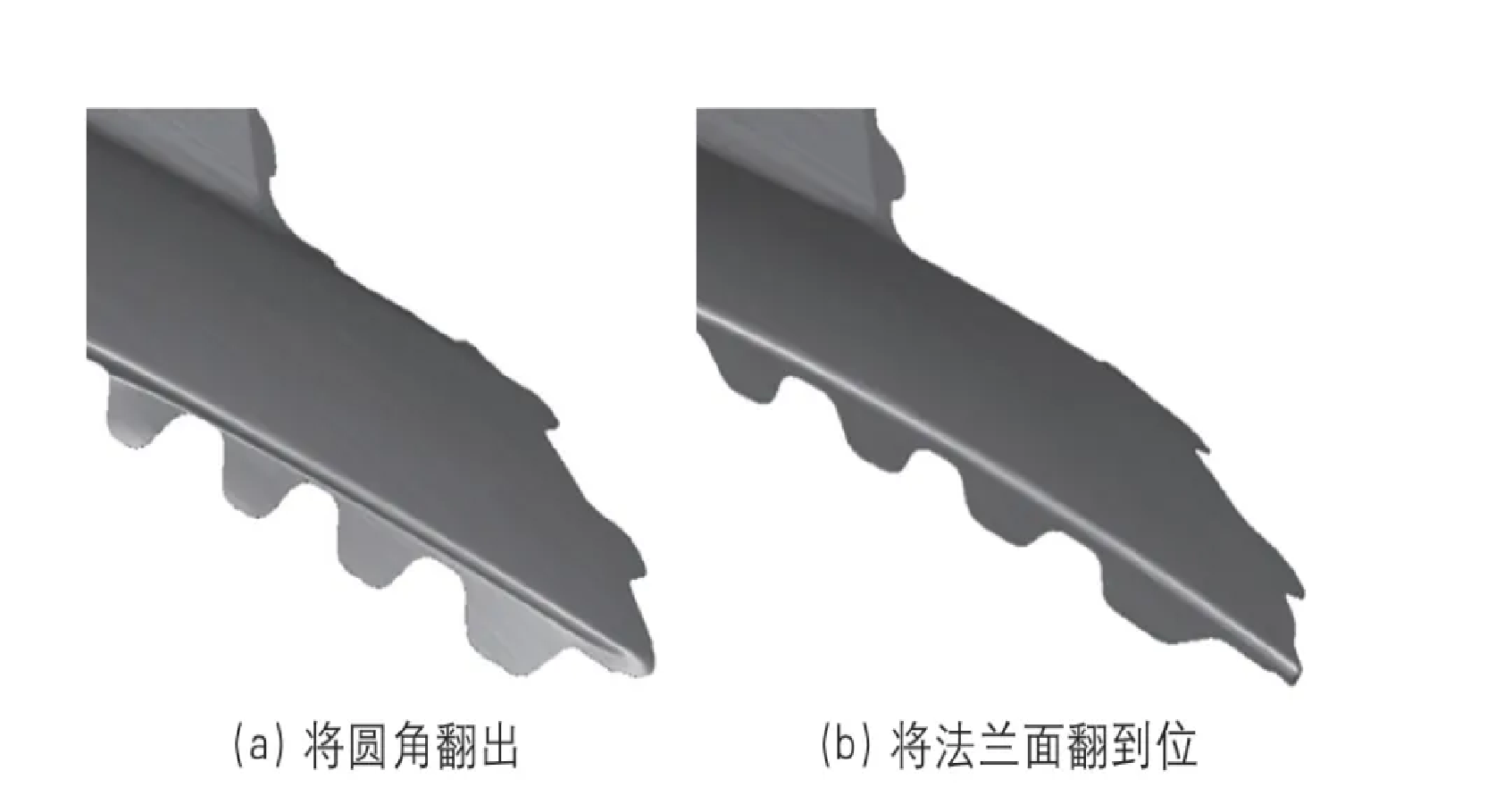
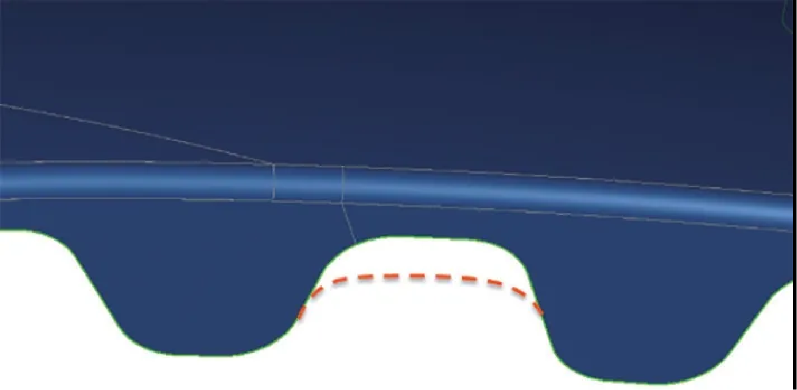
Even with the split-sequence flanging process, there is still a gathering phenomenon at the short edge (notch) position, which results in the sheet not wrapping the die and the rounded corners not being smooth, as shown in Figure 6.
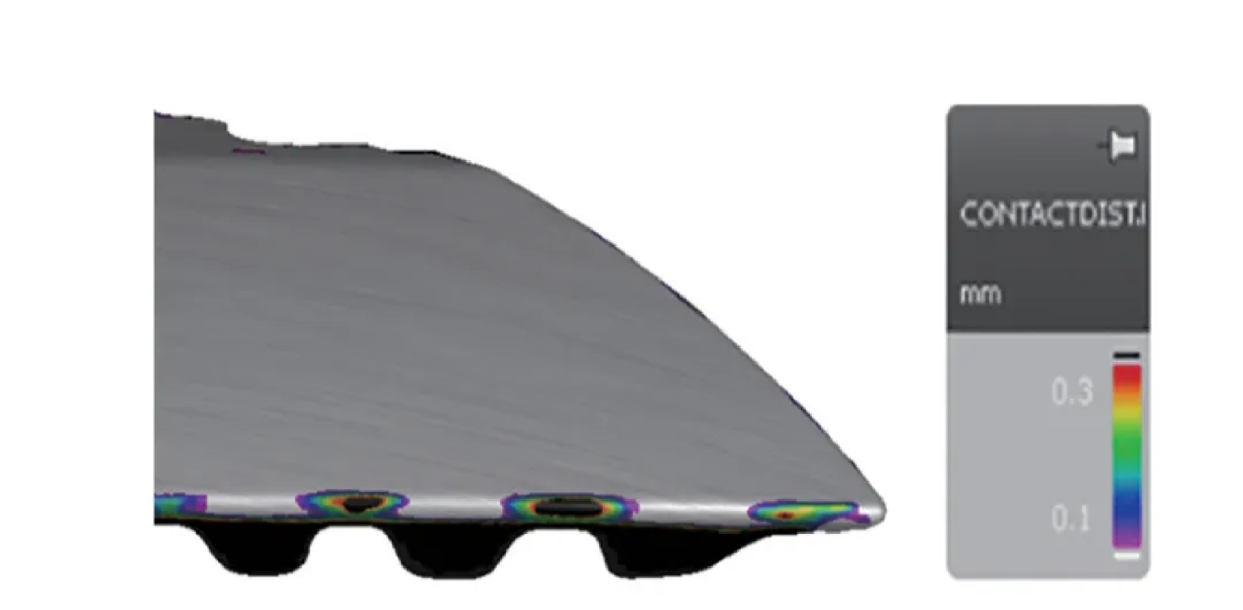
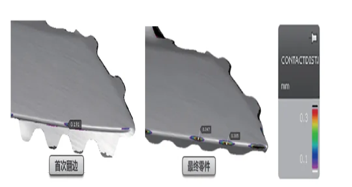
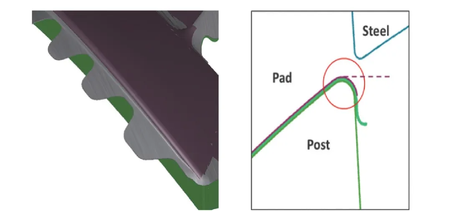
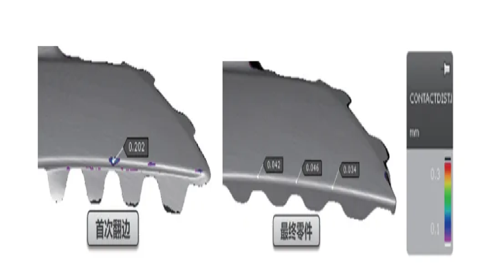
This R corner is not smooth and the short side of the poly material problem, resulting in the whole car assembly state is very poor, UQA assessment of serious demerits, affecting the assembly of the assembly (and taillight matching gap is small) and lead to the distortion of the major quality problems such as rattles. The long side of this product is welded requirements, the current length of 30mm can not be shortened; and through simulation analysis found that only the growth of the short side of the distance to make up for the length of the program, there are still defects in the face (Figure 7, Figure 8), but also can not completely solve the problem of the R corner is not smooth. Therefore, on the basis of adopting sequential flanging process, the first flanging adopts pressing material flanging (Fig. 9) and short edge position touching material first (Fig. 10), to improve the rounded corner shape, to ensure that in the second flanging process, only the lower flange is flanging, and rounded area is not involved in the molding, and finally solves the problem of R-corner not smooth and the consistency reaches 0.2mm (Fig. 11).